Slicing my inner dome!
So, finally got some time on a weekend with nice weather to get outside with the inner dome and my Dremel. Whilst the dome set I got had a laser cut outer dome, the inner one was totally uncut. The aluminium domes come as an inner and outer to allow you to have the indent around each of the panels, and also lets you have a nice lip if you have the panels opening, which is something I want. Of course, this means lots of holes to cut. Any panels that are going to open have to be cut out, as well as all the holes for the lights and holo projectors (HP).
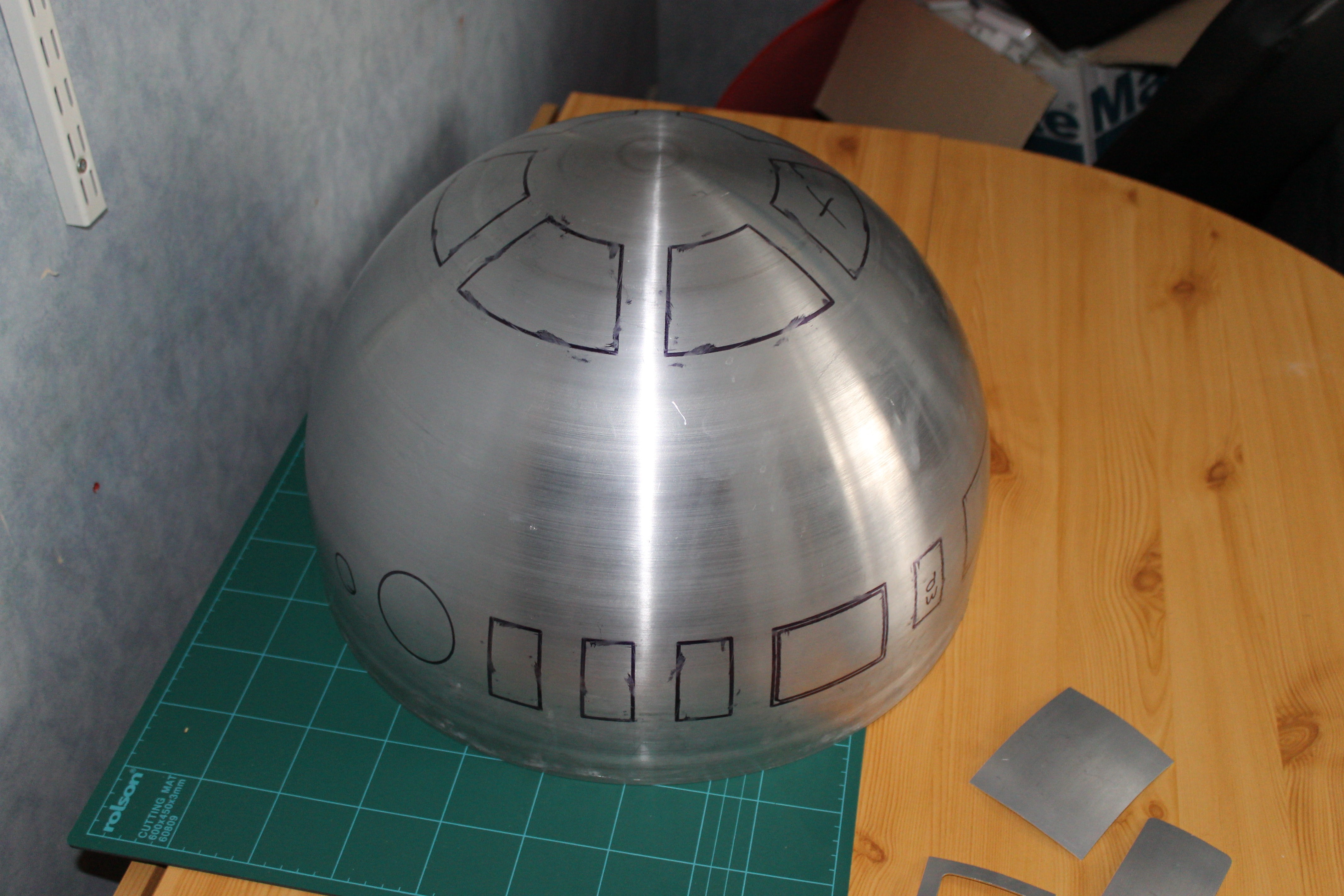 To start off with, all the holes were marked using the laser cut outer dome as a template. HP and light holes were to be the same size as the outer ones, but the opening panels need more of a lip. A tip I learnt from reading other builder’s logs was to use a large washer, and to put the marker pen in the center, then roll it around the edge of the opening. This gives you pretty much a perfect size for the lip. Next comes the scary part.
 Cutting the dome! These things aren’t exactly cheap, and even worse they’re quite hard to come by, having to wait for runs to be done of them by the guys in the states. But, its got to be done so I got the Dremel and a whole bunch of fibreglass reinforced cutting discs for it. I needed a lot as the wear down extremely quickly. I went through over two dozen of them just on the dome. Thankfully I got plenty.
I found the easiest way to do it neatly was to do the large part of the cutting with the dremel, at least enough to make a cut a few cm long so that I could get the hacksaw into the hole. The hacksaw made a much cleaner cut with more control. The Dremel had a habit of biting in and running off a bit, which made some of the fine cuts a bit difficult. By far the hardest bits to do were the circles for which I ended up making a load of straight cuts through the center to form a star pattern, then gradually cut each of the prongs off. Once I had the main parts cut I attached all the cuts with a large file to take it to the lines I had drawn.
 It took a good few hours to get through everything, but it was worth it. The holes are still a little rough and still need some sanding down with wet and dry. Also the circular holes all need to be made a little bigger. They were originally marked up to be the same size as the outer dome holes, but ideally they need to be at least a few mm bigger, especially the HPs. Another tip that I’ve found on the net is using a glass wine bottle to help with the sanding of the circular holes. Wrapping some wet and dry around the neck, you can sand in a circular motion to get an even hole.
Still left to do are the rear PSI holes, in both the inner and outer domes. It is the one outer hole that wasn’t pre-cut, so I need to be extra careful with the outer part. The current run of laser cut domes are a lot nicer, with the inner and outer ones laser cut and all just about ready to just polish and paint. Also, I think I’ve been fairly lucky with this dome, as a lot of people report having to cut the inner dome in half to get the inner and outer to fit together properly.
 Once the last PSI holes are cut I’ll be ready to bind the two domes together permanently, which is another scary one way step. I’m making sure I’ve as much done with them separate as possible to avoid damaging the outer dome with a slip of the Dremel. I still couldn’t resist having a test fit of the two domes and inserting some of the lighting. It looks pretty good.
Next main steps once its all bonded is to install the main radar eye which I’m hoping to bolt on to make it removable, and then I have to source a load of hinges which seem to be either very expensive, or hard to find.
All in all, a good weekend of work. I would’ve like to do more but due to losing an hour due to the clocks changing, an early morning call from work, and Mother’s Day, I didn’t have much time on the Sunday to do much. Fingers crossed for nice weather again next week to finish off the Dremel work outside. I might also make a start on the skins too.

