Tag electronics

Are you being served?

Ok, so along with my R2, a side project is something that will hopefully fit inside of R2 and make him even more popular. To reprise his role in Return of the Jedi he will be serving drinks, and not just glasses from a fancy tray bolted to his shoulders. He will be able to mix a drink for you and dispense it into your glass.

The idea is, to have a bunch of reservoirs in a caddy inside R2’s main body, with pipes to an automatic arm that will open a door and raise, allowing you to put your drink under it. My design so far allows for five bottles, with peristaltic pumps from adafruit (via a UK reseller, Phenoptix), some L293D motor drivers, a TLC5940 PWM driver, and an Arduino Pro mini. I still have a long way to go on the design, but I have managed to the main module constructed and the pumps installed. I’ve also got a first revision of the circuit schematic worked out, along with a PCB layout that I’ve ordered from OSHPark.

Pumps

A closeup of the pumps

The main unit is made from a series of laser cut acrylic sheets, with a central threaded rod as the main shaft. The bottle tops still need holes for the tubing to go into, and the lids will be glued to the acrylic. Refilling will be done by removing the bottom plate and unscrewing the bottles. I also need to figure out ideas to check for the fluid level so I get notified when a bottle is nearly empty.

The main control for selecting the drinks will be handled by a Raspberry Pi, talking over i2c to the arduino to control the motors. This will allow me to do an embedded web server for selecting the drinks, depending on what options are available. R2 will also have most of his communication done over i2c which will allow the drinks dispenser tie into that and control the door and dispensing arm. Other future ideas are also having a few spare bottles and QR codes as labels on them so that I can automatically scan them in so that the Pi knows what drinks are available rather than having to key the data in manually.

Main unit

The main unit.

This is my first attempt at doing an actual useful PCB. Probably many errors and will need another couple of revisions, but it is a start. The Schematics and other files can be found on github here:

https://github.com/dpoulson/drinks_dispenser

And if you’re really bored and have money burning a hole in your pocket, then the latest revision of the PCB can be bought at OSHPark:

http://oshpark.com/profiles/DarrenP

This is the droid you’re looking for.

Alright, so maybe a bit of a corny title, but I couldn’t resist.

So, at the end of May we had a trip to Milton Keynes for Collectomania. Besides meeting and getting autographs from Robert Llewellyn and Chris Judge, the other highlight was all the R2d2 droids that were running around. There was a whole collection of different astromech droids in varying states of the build process. Once I got home, and of course mentioned it to she who must be obeyed, I started looking at just how difficult these things were to build.

Initially I joined the main R2 builders club, which also has a yahoo group with lots of useful files and blueprints.The benefit of building an R2 over most other large props is the fact that there is such a large community of people who have already found most of the pitfalls. They also do runs of parts that might be beyond another builder’s skills or too expensive to produce in single units. Unfortunately, most of the talk and production is very America centric, but thankfully there is a very active UK builders group which I quickly signed up for.

After a few weeks of reading (and more reading) the forums I decided I would take the plunge. Mostly I will be keeping a picture log on Facebook and Google+, but will also write up occasionally on here.

I thought I’d first start with what I know, electronics. There are a set of PCBs available that handle all the dome lighting and runs from a single Arduino Pro Micro which gives a lot of power and flexibility. So, with the PCBs ordered, I jumped to eBay to get the rest of the components. Obviously, a lot of LEDs were needed so they were first, I needed a pro micro to run the system, and the other main component were MAX7219 chips. Now, if I was to source the chips from the UK they would have been in the order of £9 each. eBay had them for a tenth of that price. These were pretty certainly cheap knock offs, but for that price I could order way more than needed and suffer a few DOA chips.

Of course, it wasn’t that straight forward. I didn’t realise just how close the LEDs were packed on the PCBs which meant I needed flangeless LEDs. Needless to say when I received the LEDs from eBay they had a flange on the dome which meant they would not fit. Hunting around in the forums, I found a possible source of LEDs from China that were definitely flangeless. So, re-order and wait.

Whilst I was waiting for the parts to turn up I hit a bit of luck. Probably the hardest main part to make myself was the dome. There are lots of different options for these, from aluminium to styrene or fibreglass. The runs for these are fairly infrequent, especially if you want a certain type of dome. I’d initially ruled out building my droid in aluminium due to cost and the fact I’ve never worked with metal before, but someone on the UK builders Facebook group mentioned they had a dome and a set of body skins available in aluminium. It was too good an opportunity to miss, so I bit the bullet and bought them. A couple of days later they turned up!

IMG_0136_CR2_embedded

This was scary, this was starting to be a large commitment. It is fun tho, so lets carry on!


Solar!

Over the last couple of years I’ve been looking at the feasibility of  getting photovoltaic cells put on the roof of my house. I’ve only got a small amount of roof space seeing as I live in a mid terrace so wasn’t sure if I could get enough panels to make it worth while. A couple of months ago I decided to take the plunge and get a few quotes in. Unfortunately, this is where I met the main hurdle with the whole project. Despite emailing half a dozen companies, I only got two visits to give me a quote, and only one of those actually sent me a quote.

Thankfully I’d done enough research into the technology and rough costs so that I knew the quote I got back was a pretty typical price. The company also seemed to be pretty decent with some good reviews and a good web site. With all that in mind, I decided to go for it and accepted the quote. I was very impressed with how quickly things went. One of the requirements for getting the feed in tariff from the government is to get an Energy Performance Certificate (EPC) and within a few days I’d had the survey done for that and the certificate in my hands. Only a little over a week later the panels were installed, commissioned and my meter was running backwards.


Solar install

Solar install

So, what did I actually get installed? All together, 16 panels were squeezed onto my roof across two elevations with 8 on a west facing aspect and then 8 on the south facing which gave me 4kW in total. The installation is fairly straight forward and involves the two arrays of panels going into an inverter which feeds into the main circuit breaker panel. I’ve also installed a full monitoring system that keeps track of power consumed and solar power produced, which I’ll probably write about in another blog post.

The big question however is, is it all worth it? I haven’t been running them for long enough really to give a definitive answer, but from the calculations I’ve done I think the answer is a resounding yes. The feed in tariff is index linked, so will increase over the 20 year lifespan of the panels along with inflation, and it is highly unlikely that the price of electricity is going to go down, all of which means that I should have paid off the panels totally in under 8 years. I can see that number dropping quite a bit too as electric prices increase. Also, the feed in tariff runs for 20 years, but the panels should last even longer than that and are still 80+% efficient after the 20 year mark so should be providing free electricity for many years after the feed in tariff has finished. Over a 20 year period, the initial investment should see a return of over 12% which is so much more than any bank can offer.

If you can afford to get PV installed, I’d definitely recommend it. I’ve already seen a drastic drop in my electric usage and the money is much better installed on my roof than in the bank.


K40-III Laser Review

In a few other blog entries, I described getting and modifying my laser cutter/engraver. You can read these here:

Frickin laser!

This post however is a review on the laser, as it comes from the eBay seller. I’ve broken it into a few sections, and pointed out where my experience has differed from other stories I’ve heard online.

Packaging and Delivery

So, the packaging wasn’t too bad. It was obviously shipped from China, and just redistributed from Portsmouth with no actual unpacking. The outer wooded crate was quite battered and falling apart, with lots of packing tape. Thankfully, inside the crate was lots of polystyrene, and the actual device was in good shape. The x/y carriage was secured with a bit of ribbon, and all electronics were well secured. Now, from various other blogs, I know this was very lucky for me as many other people complain of loose connections and missing screws. About the only complaint I have on the whole packaging front is the way the water cooling tubes were tied in knots. This put some rather bad kinks into the tubing which could restrict the water flow.

Software

The software is the worst part of this device, which is why I threw it away as soon as I’d tested the machine was working. That being said, I can give a few observations from my short lived interaction with it. First off the software is very much Chinese with very basic translations. If you haven’t got the Chinese localisations installed on your computer, then the install process will show lots of strange characters, not that it will be much better unless you can read Chinese. This means installing the software is pretty much blind.

If you manage to stagger through the install process, you’re presented with a whole wealth of configuration options, drop downs, and a big canvas area. At this point, I managed to get one of the example files loaded and the laser tested. After that I didn’t really use the software again. I do know you can import Corel Draw pictures, and possibly even get a plugin of Corel Draw. There are lots of videos on using the software, and if you don’t want to customise the machine, you’re best off watching them.

Laser

Once again, from reading other blogs, I believe that I was rather lucky in that the test fire worked first time. Many other people have to go through an alignment process of tweaking the mirrors or even actually moving the whole laser tube. I can see why they would have these issues as this whole machine isn’t what I’d call well built. Lots of rough edges and no real finish to it in any way, but you get what you pay for. The extractor unit is very basic, and the slot for it is not a good fit. It is well worth taping it into place to get a better seal, and hence better suction to extract the fumes. For cooling you get supplied with a small aquarium pump which needs submerging in a bucket of distilled water to keep the laser cool.

The main area with the x/y axis is actually not too bad, with it all running quite smoothly. The x axis is very slightly out of alignment, which is something I still have to correct, but overall I’m fairly impressed with this. The axis are controlled by standard stepper motors, with endstops being hall effect sensors. The main drawback however is that the cutting area isn’t sealed, so the extractor doesn’t work as well as it should do.

Safety

I think this deserves a section all to itself. This device is built with absolutely no safety features at all. The laser can be running with the lid open to allow people to put their hand in the (invisible) beam of the laser, there are no interlocks either to stop the laser if the water isn’t flowing or the extractor fan fails. I could see no fuses at all within the electronics enclosure, and from one blog I read it was pointed out that some short circuits could put 20kV through to the control panel. Also, the cutting area is not sealed from the electronics area either, so fumes can easily pass through and escape.

Summary

You get what you pay for. This is a very cheap (for laser cutters) machine, with no regard to build quality or safety. If you want to get a laser cutter that works out of the box for commercial reasons, then spend three times more and get something better. That being said, if this is for someone who is technically adept and has experience in cartesian robots such as Reprap or other CNC machines, and wants something to experiment with, this could be a good purchase. My other posts describe what needs to be done to get this working to an acceptable standard, and it will cost a bit more money. I’ve probably spend another 50% on top of the original cost to get it working properly with safety features. If you do go down that route, then this can turn out to be a nice little machine for a hobby or hackspace. Once tuned and tweaked, cutting materials up to 5mm may be possible.

I’m pretty happy with it, and it was a good way to experiment with laser cutters without spending thousands of pounds. I am already thinking about going the entire homebrew route for my next one, if this turns out to be useful for me.

Upgraded Laser CNC

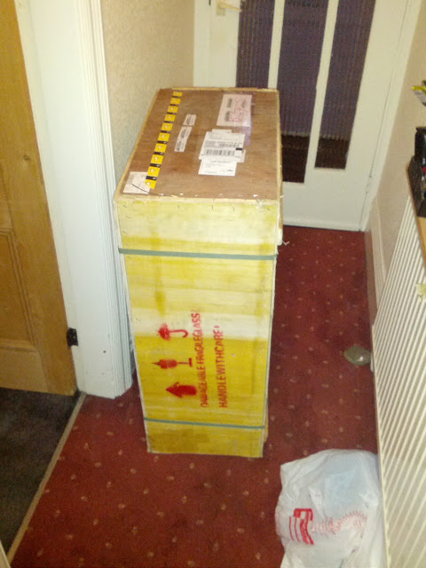
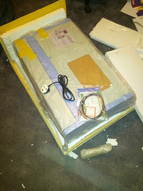
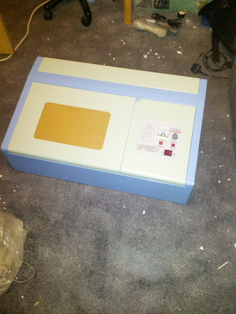
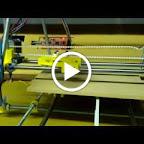
Last week I took delivery of a nice laser CNC engraver/cutter. This was a very cheap chinese machine, model number K40-III. When I got it, I knew the controller and the machine itself were very limited but there was an open hardware project call LaOS that I hoped would solve some of the issues. Couple that with a bit of my own customisation, hopefully I am going to end up with a fairly decent machine, for a lot less than a commercial model. I’m not the first to attempt this, as these machines are very common on eBay. I haven’t seen any success stories on my browsing so hopefully I will be the first.

I’m not going to put all the details on here, as I am updating the project wiki so its all in one place. This is going to be more of a log of what I do, so if you want the nitty gritty details, take a look at the wiki page for this machine.

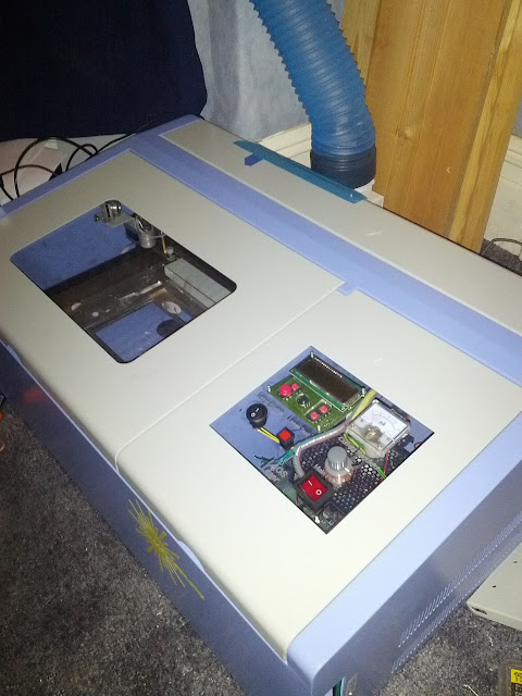
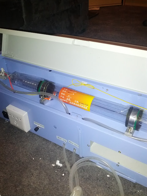
So, on with the log. After making sure it was all in working order, the next job was to figure out what all the connections did, and what to do with them. Starting with a load of photos, I started to trawl the net. The controller board I knew was a chinese model, so punching the numbers off the silk screen into Google I managed to find a pdf with the technical details. One drawback, it was all in chinese! Thankfully Google translate came to the rescue and gave me enough details, coupled with details on the Laos wiki about other laser machines, to know what each of the connectors did. The other part that needed tracing was the power supply. Thankfully this turned out to be a simple case of checking continuity between the pins and the components on the control panel. After all this investigation, I knew how the stepper motors, the endstops, the control panel, and the power were connected.

The only difficult part was how to control the laser. This is a bit I struggled with as the documentation for the LaOS project is still being written, and there seemed to be multiple ways to control the laser. One of the power supply connectors allowed me to fire the laser, which was great for testing, but it didn’t honour the laser enable/disable button which I would rather leave in place and active. There was also another connector pin that was labelled as Laser, which in theory will control turning the laser on and off from the controller board. Experimentation will be needed I think.

With this knowledge in hand, I purchased a LaOS PCB, along with the PCB for the i2c LCD addon, and started putting the electronics together. Again, due to the project wiki being fairly new, and the team behind it being very small, it wasn’t quite as easy as other projects I’ve encountered such as RepRap. I’m fairly confident this will change over time, and I know I’ll be going through the wiki adding information once I’ve got it all working.

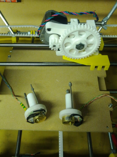
Once the electronics were constructed and ready, I unplugged the old controller, plugged in the new one, loaded up a test firmware and turned it on. I rather quickly encountered my first problem. A total school boy error of putting the wrong voltage capacitor on the board meant it blew up in my face… literally. Still, no harm was done to either the board or myself, apart from a bit of an adrenaline rush. I quickly swapped out the old capacitor with a newer one of the correct voltage and plugged it all in again. Nothing blew up this time, and I could confirm that all the voltages seemed correct. Next step was to try some of the motors and end stops. Moving the head back and forth showed that both home position endstops were working fine thankfully, and were inverted so that they turned off when homed. I guess its safer that way, and it told me I needed to set that up in the configuration.

Happy that things seemed fine, I put the real firmware onto the board and fired it all up. Success… kind of! The X axis homed nicely, but the Y axis sat and juddered in place. After a few posts on the forums, and a lot of messing with config files, and checking of connections, finally it homed to the correct position. With that seeming to work, I fired up the interface software called visicut, and tried to send a few test files to the machine. Well, things moved, but not exactly in the right way. Still, better than nothing and I was fairly certain that it was all down to settings in the config file. I was beginning to understand that the config file is the hardest part of setting it all up, but finally after a lot more tweaking of the file, I had both axis moving in the correct way and the correct amount.

Next came the laser. In some ways, I was dreading this. So far I’d been messing with things I knew about from building a couple of reprap machines, namely stepper motors and pololu stepper drivers. I was fairly confident if I blew either of these things, then I could fix or replace them. The laser was something totally new. However, from reading the documentation, and putting a multimeter onto the connection marked L on the PSU, I was fairly certain all I needed to do to active the laser was to pull the L pin down to ground. All this took was a single wire from L to one of the Laser On pins on the LaOS board, and the other Laser On pin I simply tied to a handy ground point (ie, the screw terminal on the board that came from the PSU ground).

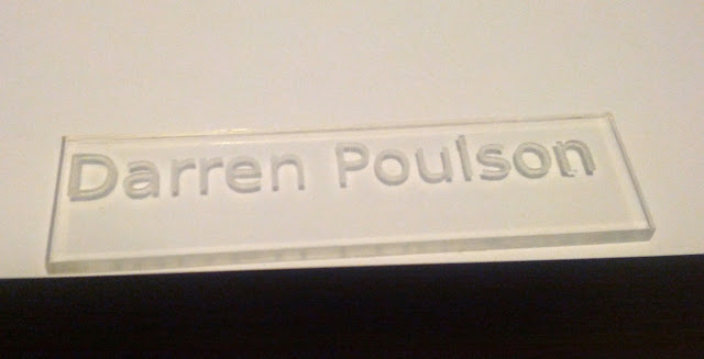
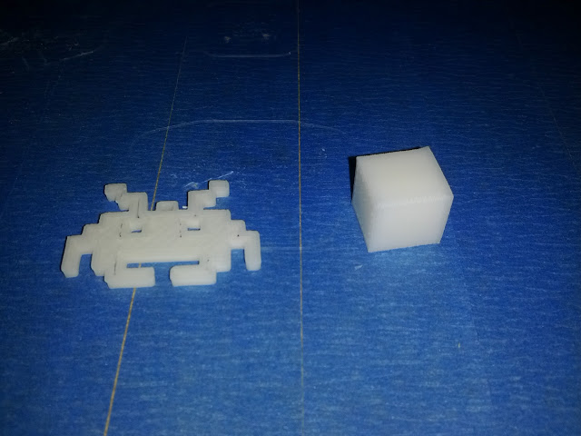
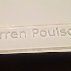
With a little bit of trepidation, I powered up the printer and started visicut. I loaded a simple rectangle file to test with, and hit the execute button. A nice little rectangle was cut out of the test bit of card! Wow, that was easy! To say I was happy would be a little bit of an understatement. I quickly grabbed a bit of acrylic I’d got to test with and fired up inkscape to draw something. I only wanted something simple, so I decided to try and engrave my name into the acrylic, so a quick click on the text button, and I typed my name in. Up to the extensions menu, and select Lasercut Path and the image I created was loaded up in visicut. A click on engrave, and execute, and my name was being etched into the acrylic! It turned out rather nicely! 🙂

Frickin laser!

All in all, I’m very happy. I got a cheap machine off eBay with a lot of limitations and with the help of an Open Source hardware project, I’ve turned it into a networked laser CNC machine. It is still limited in the strength of the laser and the bed size, but I now feel confident enough that if I end up using it a lot, I can get a higher end cutter and convert that.

I’ve still got a way to go yet on this project. The CUPS driver isn’t working properly, so I’m relying on using visicut to do the actually printing work, but that isn’t too bad as it is a pretty easy to use program. I also need to put PWM onto the laser output so that the controller board can vary the laser cutting power itself. Lastly, there is the i2c LCD module to get working. For some reason if I plug the module in, the controller board won’t boot properly, but I haven’t done any investigation yet to find the reasons. Oh, and I think a few safety measures are needed such as a water flow sensor and lid sensor which deactivate the laser in the case of anything not working… better safe than sorry!


Lasers! Pew Pew Pew!

So, the other day a large crate arrived on my doorstep.

Frickin laser!

Hmm, what could this be?

Yep, I treated myself to a new toy. A 40W CO2 powered lase CNC engraver/cutter (Model K40-III). Now, this isn’t exactly a top of the line model, infact it is probably the cheapest you can get one without going down the DIY route. It is a very cheap device from China, with the most basic of functions. Basically an X/Y axis with a couple of stepper motors, a 40W laser, and a very basic controller board. The main drawback (besides all the instructions being in Chinese) is the fact that it will only work with the rather rubbish software that comes with it, and that will only run on Windows XP. That isn’t going to work for me, especially after finding an old XP laptop and trying the software out. To say that it is buggy and un-userfriendly would be an understatement.

Thankfully, I knew this before purchasing it from eBay. There is a great open hardware project call LaOS, which is designed to replace these cheap and nasty controller boards on these types of lasers. So, armed with a PCB from the project, a bunch of components, lots of pictures of the existing setup, and my trusty multimeter, I am going to set about installing a nice LaOS board. The benefits of this new board is the fact that it adds network capabilities. It becomes effectively a network printer, controllable from a linux machine as a Cups based printer. This way, programs like Inkscape to draw the desired output, and send it to the machine. A much easier way to control it.

An LCD display with local controls is also available as an addon to the main LaOS board. All in all it should turn this cheap basic machine into something fairly usable. It should then be able to compliment my printer for making things, and Joy should also be able to use it for some of her arty stuff.

Testing!

So, first stage was to do a few tests to make sure it had survived the journey and was in a working condition before I break it. The front panel has a handy laser test button to let you fire the laser without having a computer hooked up. Needless to say, after hooking up the water pump to cool the laser, I had a bit of fun burning things! 

Frickin laser!

Seems to be working ok

And with it hooked up to a computer with the rubbish software

Frickin laser!

About the best I could do with the software supplied

All seems good, so time to take it apart! Hopefully the next post will have a nice success story of a much improved machine

Frickin laser!

Unboxing!

Frickin laser!

Unboxed!

Frickin laser!

Thats a 40W Laser


Second part is here

Nearly there! The hotends have arrived!

I got a nice parcel delivered today. Two nicely build hotends for my new Prusa Reprap. After all the issues with the Huxley, the Prusa has been a total doddle. The last piece I needed for it was a hotend, and after having some issues sourcing some of the components, I had a look on eBay for any pre-built ones. I found one guy shipping some from Poland that looked perfect for what I needed, not only did they have all the molex connectors already done in a way that is compatible with my Sanguinololu board, but he was offering a twin pack with one .5mm and one .25mm nozel. Oh, and a pre hobbed bolt too!

Prusa build

So, with the body built and the electronics tested, all I have to do is figure out how to attach the hotend and I can start building. I’ve already posted a video a few days ago of the body moving nicely, which is further than I ever got with the Huxley. Never know, maybe by this weekend I’ll be able to print something! Just have to finish work first.

Here’s the video of the first test of the electronics.

Prusa build

Replacement electronics are here!

The replacement electronics for my Reprap Huxley arrived today at long last. I’ve had them plugged in for nearly an hour over dinner, and no flames. Good start!

I think this evening and weekend are going to be devoted to trying to get my printer working. I hope nothing else turns out to be faulty with the kit I bought. I’m already very disappointed with the quality of it overall. If I had a better understanding of the whole Reprap process, I would have gone with just ordering the plastic parts from somewhere and building my own. I’m sure I’ll do a full write up on it at some point.

To recap, I’ve got the frame built with all the stepper motors mounted and the belts in place. So all(?) I have left to do is:

  • Calibrate the electronics
  • Finish the extruder – Just needs the motor mounting I think, and the tube inserting.
  • Finish the hot end – All gunged up, just needs the electronics attaching to the nichrome wire and thermocouple.
  • Mount the hot end
  • Mount the end stops

Once all that is done, I may actually be able to start testing. The testing is going to be a long process I think, I very much doubt I’ll be printing quality objects from the start. Lots and lots of wasted plastic doing test prints, levelling the base, etc. Still, if I can finish this weekend with an actual printed object I’ll be happy. Roll on 5pm when I finish work!

Hobby electronic links

Since deciding to renew my interest in electronics over the past few months, I’ve tried various websites for supplying components and parts, along with some good sites for learning and ideas. I thought I’d do a quick write up of some of my favourites and put it all in one place.

Firstly, lets start with components. You will always need somewhere to get all your bits from, as well as tools and consumables. Here’s a few sites that I’ve found both handy and reliable. I do like to be able to get everything I need from one place, but I haven’t yet found a one stop shop for everything, but I have managed to narrow it down to just a few that will satisfy most of my needs.

  • Bitsbox – This is a great site to get your basic components from. They are cheap, well stocked, and have a nice simple website to use. You won’t find things like Arduinos, or Sparkfun kits, but you will find just about all the basics you could ever need. Components can be ordered in singles, or bulk, and delivery is pretty rapid. I tend to use Bitsbox to stock up on standard things like resistors, capacitors, common chips, and other non specialist components.
  • Proto-Pic – This is where you go for the more ‘building block’ style components. Things like Arduino, Sparkfun, sensors boards, breakout boards, etc. Great place with a nice easy to use website. I do find that I need to watch my spending here. It is too easy to keep loading up the basket with fun parts, especially shiny things like LEDs. There is a lot going on now in hobby electronics where you buy pre built component modules and link them up for a project, rather than scratch built circuits. Good communication from the staff here, and will part ship your order if they are having trouble with stock, instead of having you wait.
  • Cool Components – Very similar to Proto-Pic. You should be able to find what you want in one of these two stores. I’ve dealt more with Proto-Pic than Cool Components, but more for familiarity than any other reason.
  • Jeelabs – This is a slightly odd case, and is a more specialised shop than the rest. I’ve been working a lot with JeeNodes, and this is the place to source them from. Its a one man shop, but he is designer, builder, and shipper. He also provides a lot of information, not only on how to use his products, but also in general electronics knowledge.
  • Unmanned Tech – Not exactly in the electronics section, but this is where I get my quadcopter autopilot components from. I just wanted to mention it here because the support that is given is great. Very friendly and actually want to help.

Next, lets look information sites. These are places to go for learning more about electronics, techniques, and news.

  • Jeelabs Blog – As mentioned above, Jeelabs provides JeeNodes, along with other modules to go with them. The blog provides a lot of information about how to use their products, how they were designed, and also general information such as circuit design, how to improve your arduino sketches (especially making them low power), and walks you through good ways to measure and bug trace your own circuits. Well worth following.
  • EEVBlog – A great, fun blog by a mad aussie. (Are there any other types?!) He has a regular video blog on a fairly wide range of electronics subjects, including reviews on lab equipment, tear downs of new gadgets, and instructions on circuit design. He’s now making a living from this blog after having many years work experience in electronics. Videos are released on a pretty frequent basis and are well worth a watch just for his enthusiasm!
  • Instructables – This site is just fantastic. People from all over the world with a passion for making things can upload full build instructions to this site for all to read and reproduce. Its not just electronics here either! Anything that involves making things can be found here, from needle work to metal work! The information is free, but it is worth signing up for a full members account which allows you to view the instructables in a single page, rather than multi-page, and also download it as a PDF. Handy for putting onto an e-reader or similar. Great place to look for ideas for projects, or help on something you’re working on.
  • Makezine – Makers are taking over, and this is the place that pretty much summarises the movement.
  • Thingiverse – If you have a 3d printer, laser cutter, or cnc mill (or at least access to one), then you can find many actual objects available to download to be produced. The idea being, if you need something, and design it, you can then upload it to this site for anyone else to produce for themselves. An open source object library.

Thats it for the main part. A few honourable mentions go to RepRap for all your 3d printing needs, and also Youtube. There are many many videos there that are well worth a watch.