3d Roadblocks

Okay, its been a little longer than I hoped for for an update, but it has been Christmas so I’m using that as an excuse.

The build of the huxley was going very nicely until I hit a few snags with the kit I’d ordered. Firstly, there are nowhere near enough nuts, bolts and washers provided to complete the kit. I ran out before I’d even finished the frame, let alone mounted the motors, built the extruder, or made the idlers. Huxley
Secondly, the belt for the X axis was too short, so I couldn’t fit that.

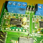
Thirdly, the electronics actually burst into flames on me whilst testing and configuring the motors. This was before I’d actually done anything bar plug the power supply in. To say I wasn’t impressed doesn’t quite cut it! Oh, and the analogue to digital converter for the hotend was missing.

So, considering I got a kit for hassle free construction of my first printer, I’m not overly enamoured with it. The UK company have put me in touch with the manufacturer to get things sorted, and they have said they will send out the replacement/missing parts from the states, so hopefully things will get sorted, but I could’ve had a nice working 3d printer by Christmas had everything been right in the first place. The instructions on the wiki also leave a lot to be desired, especially the hotend page, which were for a totally different design. Only one photo showed the model I’d got.

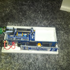
In the meantime, whilst waiting for the replacement parts, I’ve done some research into the electronics available for the various reprap machines, and have decided to build my own electronics based on the generation 7 schematics on the wiki. These electronics all fit onto a single sided PCB, so nothing complicated, and seem to be relatively simple. In fact, I bought a pre-made board off eBay, and had most of the other electronics already ‘in stock’ in my cellar. The gen 7 boards also use pluggable stepper motor drivers, which mean that if one does burn out, then you can simply plug another one in, unlike the kit electronics where everything is surface mounted and impossible to replace.

With all this, I’m hoping I can get a chance this weekend to finish off the electronics and get the main body of the printer working. I’ve built the extruder, mounted the motors, and got all the belts on, so all that is left is the calibrate and level it all, and build the hotend. I’m hoping the hotend will be fairly straight forward, but as I’ve no real instructions, just one picture to go off, I’m going to be very careful!

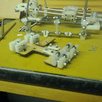
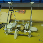
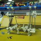
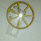
Anyway, here’s some pictures!

Huxley

Main frame

Huxley

X Axis

Huxley

Y Axis

Huxley

Y Axis in place

Huxley

X and Z Axis in place

Huxley

Extruder


In other news, I’ve been rather impressed with how easy Google SketchUp is to use. I’ve been messing around with it to design the parts for me printed quadcopter. For a beginner who just wants to make simple parts to be printed on a reprap, it is perfect. Install the plugin for exporting to STL files, and you can both upload these to thingiverse, and import into most of the 3d printer software that is available for the repraps.

Also, slightly related, I’ve actually had a quadcopter flying with the Arducopter controller. It was only a brief test as I managed to crash it and shatter 3 of the blades. Spare blades only arrived on Christmas eve, so not had a chance to do much more with it. Just waiting for some better weather so I can fly it outdoors. I’ve managed to snag myself and OpenPilot Copter Control board too last week which should be arriving any day. This is a halfway house between a simple KK Multicopter controller, and the full blown ArduPilot Mega. I’ve got the APM telemetry kit coming soon too, so I can take my laptop and get live telemetry from my quadcopter. Unfortunately, my laptop battery has developed a fault, so the only way I’ll be able to do that at the moment is if I can fly it somewhere with a power socket nearby!

So, hopefully next week I’ll be reporting that my printer is done, and will at least have done a couple of nice test prints. I think my first actual things to be printed will be brackets and improvements to the printer tho’.
The construction begins…

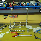
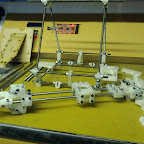
Two parcels arrived this morning, one a 2.3kg reel of 3mm ABS filament, the other was a surprisingly small box full of plastic and metal. Otherwise known as a RepRap Huxley 3d printer! A little over 3 weeks past the expected delivery date, but at least its here now.

Unfortunately, work got in the way of me doing much, but an hour of my ADSL being broken over dinner meant I could at least open up and check the contents. I must say, it is smaller than I was expecting, but thats a good thing. This should fit nicely on my desk and not take up too much room. The box contains everything you need to build the printer, bar tools of course. This kit is actually an import from the states, sold through a UK company who I assume buy a load of these and then ship them out locally. It did come with a US power cord on the PSU, but for me that isn’t exactly a show stopper! No instructions are included, instead everything you need is online on a wiki, and in numerous videos supplied by other people who have built them and in true open source fashion, contributed back to the project. In this vein, I’m hopefully going to improve the instructions on the wiki a little. I’ve already spotted a few areas that could be improved.

Wonder how long this is going to take me!?

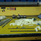
Huxley

Plastic parts, and metal rods.

Home Monitoring

Over the past few months I’ve been slowly stocking up on all the equipment needed to properly get back into electronics. As I was gathering things together I discovered Arudinos. These are an easy entry into microcontrollers, much simpler in my opinion to PICs, and cheaper than most other developers kits. The fact that they’re open source and open hardware just seals the case. The standard Arudinos are rather nice to work with, but since messing with them on a few mini projects to teach myself about them, I came across a guy who was selling his own custom design, utilising the arduino bootloader and interface, but in a much smaller form factor and inbuilt wireless communications.

These JeeNodes are about the size of a pendrive, and have an inbuilt RF12B wireless module. Along with the nice hardware design, there are also some easy to use libraries, and a great website to accompany them, with lots of nice tutorials, information, and general geekiness.

Home Automation

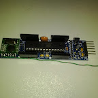
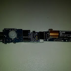
So, where does home monitoring come into this? One of the addon boards that Jeelabs sell are little room monitoring nodes that detect temperature, humidity, and light level. Add a PIR and you’ve got a motion sensor too. The guy behind the JeeNodes, Jean-Claude Wippler, has done some great work on power consumption meaning that these room nodes can run off a single AA battery for nearly a year. There are about a dozen or so of these nodes now spread across my house, logging into a database, and I’ve done some basic graphs to display the data.

Home Automation

Now I’d also noticed another project using arduinos to monitor electric consumption that was also based on JeeNodes, and reporting back to a central server to log into a database. This got me thinking, could I combine these, and maybe more. The beauty of open source is the fact you can tweak and edit to your hearts content. The fact that both these projects used JeeNodes, and more importantly, the RF12B library from JeeLabs, means that I only need one receiving station and a few small edits to the nodes.

To the transmissions I added a node type to the beginning of the data. This defined whether the node was a room node, power node, or any other future node types I may define. Most of the rest of the code was left untouched, except to assign a node number to each node. That was the easy bit.

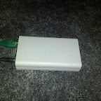
Next I needed a receiving station, and some way to get the data it received into a database. For this I once again turned to the JeeNode. Handily, JeeLabs also sell a nice case for the JeeNode, along with a Ethernet add on. This gives me a very small self contained module that simply needs power, and an ethernet connection. Both the energy monitor project, and the room node project had their own code for a base station, and for getting the data into the database. In the best traditions of open source, I have stolen from both these projects and combined my favourite ideas out of both.

The houseNode sits and listens for any broadcasts from any nodes. It knows about the different types of nodes, and the data structure to be expected for those nodes. When a data packet is received then the node type is stripped out, and the rest of the data put into a structure definition depending on the type. Then a JSON structure is constructed, and sent via HTTP POST to a web server. No acknowledgements of data being received are currently sent, but with future expansions that I have in mind, this will be a requirement.

Home Automation Home Automation

The web server will receive the POST command, and basically dump this information into a database. From this database, a front end can draw graphs and report on anything you want. The front end is very much still in construction, but can be viewed at http://home.22balmoralroad.net/

Future developments I am considering are a thermostat node, to control our central heating, and RFID entry/exit nodes to log in and out of the house. The RF12B modules have a limit of 32 addresses, two of which are reserved. However, 30 nodes should be enough for most of my ideas! It does have the other benefits of very low power, very simple, and the JeeLabs library even has encryption built in. Below are the Arduino sketches for each of the nodes.


My Cellar

My Cellar, AKA the command center!

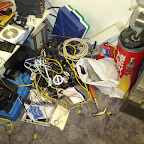
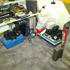
I’ve had a fairly productive weekend sorting out my cellar, ready to crack on with some of my projects, although strictly speaking sorting out the cellar was actually on my list of projects. Besides the standard cleaning up of all the mess, including a good hoovering, was the final vanquishment of the cable monster. I know he’ll come back at some point, but I’m hoping that with enough will power from me to actually put things back where they belong, his return will not be for a long time.

Before (Already was beaten down from his full might about 3 months ago!):

The Cellar

Now:

The Cellar

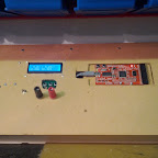
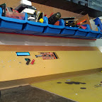
Next on my list of projects down here is the construction of my workbench panel. I want to embed a load of my equipment permanently along the back of the workbench, so for this I knocked up a quick frame that allows me to start mounting some of my tools. So far I have my digital power supply and OpenBench logic sniffer. The digital power supply is one built from a kit available online from Tux Graphics, which is a nice little variable current/voltage power supply, powered by an old laptop PSU, and controlled with an Atmega8a microprocessor. It will also hook up via usb to a computer, but unfortunately a slight design error in the placement of the power switch prevents me from doing this at the moment. The OpenBench logic sniffer is an open source logic analyzer hardware design.

The Cellar The Cellar The Cellar

I also want to embed a few other tools into this panel, such as a multimeter, frequency counter, usb hub, signal generator, and just about anything else that is useful and will cram in here.

In other projects, still waiting for me 3d printer to arrive. RepRap Central said to allow 3 weeks for delivery, but so far it has been over 5 weeks. I’m not impressed at all, and if they weren’t the only place I can find in the uk to get the complete kits from I would be going elsewhere. I’m hoping it arrives next week at some point, as I want to document the build process for this web site. On the quadcopter front, I’m beginning to think I’ve got a faulty controller board, or at least a faulty gyro on the board. I’ve ordered another one to give this theory a test, and if the new one works will get it replaced. Not really going to be a waste of money getting another as I’m sure I’ll be building a few. Once I have this first one off the ground, a bigger better one will be in the pipeline with full arducopter control, which includes gps, telemetry, and full autopilot!

So, thats two posts in to weeks. So far so good! 🙂

My Android G1

Well, I’ve had my Android G1 phone for a little over two months now and thought I’d write up my findings, and also put together a few tutorials on what I’ve done to my phone.

From day one, I’ve been impressed with my phone. I can’t comment on how different the cupcake (1.5) software is different from previous releases as mine came pre-upgraded, but from all accounts it was a major step forward. I have since rooted my phone and put some experimental builds of the operating system on it with fantastic results.

Once I’d uploaded my contacts to gmail, the phone automatically synced up with my account so all my contacts were available within a couple of minutes. I would’ve liked to stay using my own syncml server in egroupware, but google does make things a whole lot easier, as well as being a little more reliable than my home broadband! Also included in this sync was any calendar entries.

The general feel of the phone is quite nice, with the smooth touch screen interface working well. Not as slick as the iphones that I have seen, but then it is a lot cheaper. About the only criticism I have had with the phone is the abysmal battery life, this however has been fixed as I will mention below.

After using it for a few days, trying various applications from the market, and generally doing the usual new phone things, I decided it was time to break it! First on the agenda was rooting it. Underlying everything it is a Linux distribution, with all the geek fun that that entails. Rooting gives you access to the internal flash and allows you to do all sorts of fun things with your phone, most important to me was the ability to upload custom ROM images. A good guide to rooting your G1 (along with a lot of useful information) can be found at the xda developers forums.

After a bit of hunting around, I found what seemed to be one of the best ROM images to try buy a guy known as JesusFreke. Putting a custom ROM on your G1 once it has been rooted is a piece of cake. Simply drop the ROM image (update.zip) onto the root of an SD card, boot up the phone whilst pressing home and power which will drop you into a boot loader from which you can flash with the new ROM. Occasionally you will have to wipe all information from the phone, but that’s what backups are for!

Custom ROM images tend to have a few extra applications built in, and little tweaks here and there. Most importantly they do tend to improve the poor battery life. I ran with the JesusFreke ROM for a few weeks quite happily, until I came across another ROM image that seemed even more fun.

Whilst looking for info on the Android Donut release, I came across a guy called Cyanogen who had been back porting a lot of the new experimental Donut code, back into Cupcake. This included things like extra widgets, speed improvements, updated apps, and battery tweaks. I downloaded the latest experimental ROM and flashed my device with it. I’m glad I did. Battery life for me had started around the 5-6 hour mark when I was being conservative with phone usage and things being turned on. With JesusFreke that had extended to maybe 7-8 hours. Putting Cyanogen’s new ROM on has just about doubled the battery life. I’m easily getting a full days usage out of the phone without having to power save by turning wifi and bluetooth off constantly.

I’ve just put the latest version on (3.9.11.2) which now includes the global search function demoed at the Google IO conference earlier this year. One search bar will now search the internet, contacts, market and applications, with more applications tieing in as they are updated. Also included by default is apps2sd which installs apps to your SD card to save phone memory (if you partition your SD card correctly), linux swap on SD (again if your SD card is partitioned), compcache which greatly increases cached items performance, as well as so many performance increases you won’t believe the speed difference from the standard ROM.

All in all, the standard G1 is a great phone, just let down by poor battery life. A rooted/modded G1 using Cyanogen’s experimental ROM is probably the best phone I have ever had. If you have a G1 still running the stock ROM, all I can say is it is worth biting the bullet and getting a custom image put on it. Yes, there is a risk of turning your phone into a rather expensive plastic brick, but in my opinion it is worth it.

Hopefully I will write up a guide to how I’ve updated my phone incase anyone wants to do something similar. Also, I’ll probably have to do the obligatory list of apps that you should need!