Archives August 2017

My Own Lightsaber

R2 is progressing nicely, solar stats are gathering, and I’m waiting for parts for my powerwall project. To add to the list of projects, and to learn techniques on the lathe and mini-mill, I’ve decided to build my own lightsaber.

If you want a lightsaber, there are plenty of options. Cheap ones, off the shelf decent ones, upgraded ones, custom ones, and even kits. As I want to learn machining skills I am going down the custom DIY route.

Saber Parts

A saber in its simplest for is:

Sound Board

This is a small board with an accelerometer, LED driver, speaker driver, and a couple of inputs for buttons, with a microcontroller to tie it all together. From research and conversations with my friend Neil (who has his own saber shop, London Sabers) I decided to go with a sound board from a company called Plecter Labs. This is a home run shop that produces a range of sound boards of differing complexity. The boards can be bought in the UK from JQSabers. That is also where I got a lot of the other parts that I needed.

Lightsaber sound board wiring test

Test wiring of sounds board and other components

LED

These days you have a choice between a single LED cluster in the hilt, or a string of LEDs that run up the inside of the blade. With a string of LEDs you can have a gradual light up of the blade that looks more like the film, but with a single LED cluster in the hilt it makes the blade a lot easier to remove. To keep things simple, my lightsaber will just have a single LED cluster in the hilt. I’ve gone with the Tri Cree XP-E2 which has two blue and one white LEDs on a small circuit board. The white LED allows for something called ‘Flash On Clash’ which, as  it sounds, means that when the sound board detects that you’ve hit something, the blade will pulse with an extra white light.

Lightsaber LED with wires soldered on, ready to be connected to the sound board.

Tri Cree LED

Hilt

This is the part that will be 100% custom for me. There are modular options available, or replica ones if you want something from the film. I’m doing a totally custom design and will all be machined by me on the lathe and mini-mill. It will be a fairly simple design (for this one at least) as my skills on the lathe are not exactly the best yet.

Lightsaber 'emitter' after it has been turned on the lathe and given a light polish

Emitter end of the hilt

Adding some fine grooves into the hilt of the Lightsaber on the lathe.

Turning the main part of the hilt, adding some cosmetic details

Blade

The blade is just a simple tube with reflective film on the inside to give a smooth lighting. As I want to be able to hit things with my lightsaber, I’ve gone for the thick walled dueling blade.

Progress

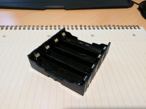
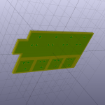
So far, I have made the emitter and main part of the hilt, along with doing a test wiring of all the electronics to go inside of it. Quite pleased with how the hilt is coming along, I just need to wait for my new mini-mill to turn up so that I can accurately drill some holes and create areas for the switch to sit. The pommel end of the hilt still needs to be designed, and will house the main speaker. Currently I’m working on some laser cut parts that will hold the internals in place, yet still be easily removed for servicing.

Laser cut parts to hold the guts of the lightsaber

The start of the skeleton for the internals

18650 Power Wall

The next step in my solar power quest is to get a decent amount of storage. To that end, I’m attempting to make my own 18650 power wall using all the recycled cells I’ve been harvesting.

Power Wall Design

I’ve been watching a lot of DIY power wall projects, including HBPowerwall and Jehu Garcia. Unlike my batteries for R2 which will be charged and discharged with me present, a power wall needs to be left unattended for extended periods of time usually. Mine will be in the garage and I’ll only be physically present when working on projects in there. This means that I need to add some extra safety features into it such as fuses.

Fuses and holders

4 x 18650 Holder

4 x 18650 Holder

A lot of people have been soldering fuse wire directly to the 18650 cells, but this is something I want to avoid. Firstly, this runs the risk of ruining the cell. Secondly, I’d like to easily be able to swap out failed fuses and cells. One person I’ve been watching on YouTube is Adam Welch who had a nice idea on how to solve both these issues. I’m extending on his idea by using fuse holders and standard 5x20mm fuses. Along with this I will be using some standard PCB mount 4 x 18650 holders.

The holders will allow for quick swapping of any dead cells, not that I’m expecting that to happen too often but I am using recycled cells with unknown service life.

PCB Design

To make this a bit more professional I’ll tie all this together with some custom PCBs that I’m currently getting made. The PCBs will join two holder trays together and mount the fuses to them.

Bottom side of 18650 Power wall PCB

Bottom side of PCB

Top side of 18650 Power Wall PCB

Top side of PCB

There will also be an edge connector designed into the PCB. The final idea will be for modular shelves that can be added into the main battery as I build them by making a backplane that they plug into. The backplane will have rows of sockets, and also house the BMS system that I want to add to further protect the battery and cells. It also gave me a chance to try out KiCAD rather than Eagle CAD that I had been using for projects up to this point.

Aims

Whilst this approach won’t be anywhere near as energy dense as something like the HBPowerwall project has accomplished, it should allow me to have a nice small scale, safe, installation.

No way I’ll ever do something like this tied to the grid, but it should be enough for lighting and charging my tool battery packs at least. With only 100W of solar panels at the moment, a single bank of cells will give me a little more energy storage than the two SLA ones. Adding a second will hopefully take this up to about 400Wh of storage. More than enough for my needs.

Still messing with the monitoring of the solar, seems to be working ok so far. However, there is currently no load on the charge controller which means it enters float charge and doesn’t show the actual amount of energy I could produce. I’m going to start wiring in a load of some form to get better stats.